An engineering history · 2025–2026

Building the
Classic Room
audio-visual system

How a multi-room Q-SYS networked audio, video, and control design became a deeply documented, operator-focused system—one screen, script, signal path, and field decision at a time.
4connected spaces
8 mo.of saved designs
v1.6.28current handoff
01Foundation02System architecture03Interface build04Integration05Reliability06Field checkout07Safety behavior08Installation readiness09System refinement10Current refinement
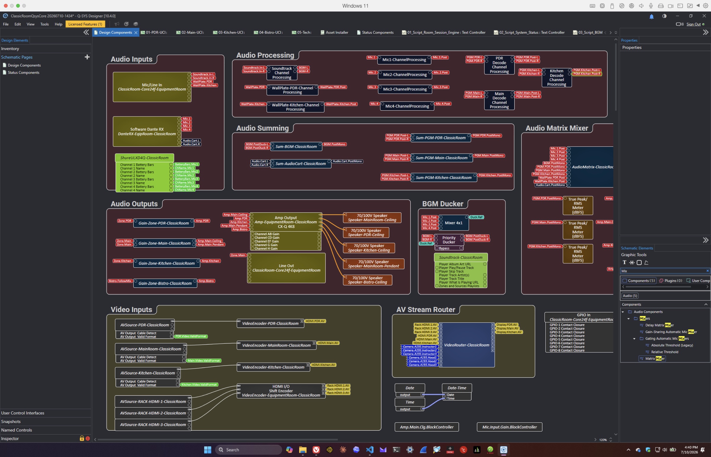
Classic Room Q-SYS Designer schematic showing audio processing, outputs, video inputs, and network routing
The implemented designThe working Q-SYS schematic brings audio processing, video routing, amplification, and room outputs together in one coordinated system.

From removal to commissioning

The design leaves
the screen.

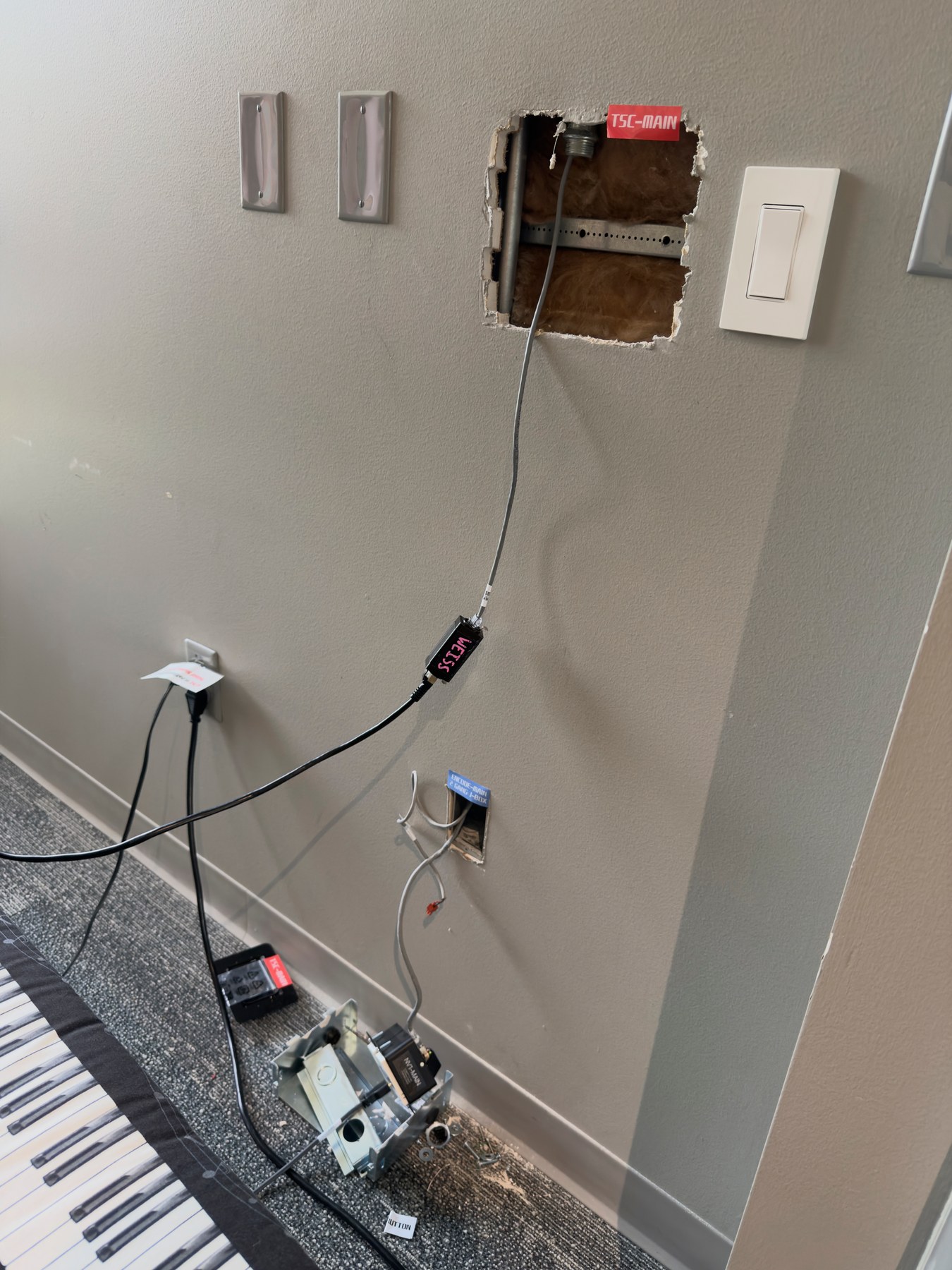
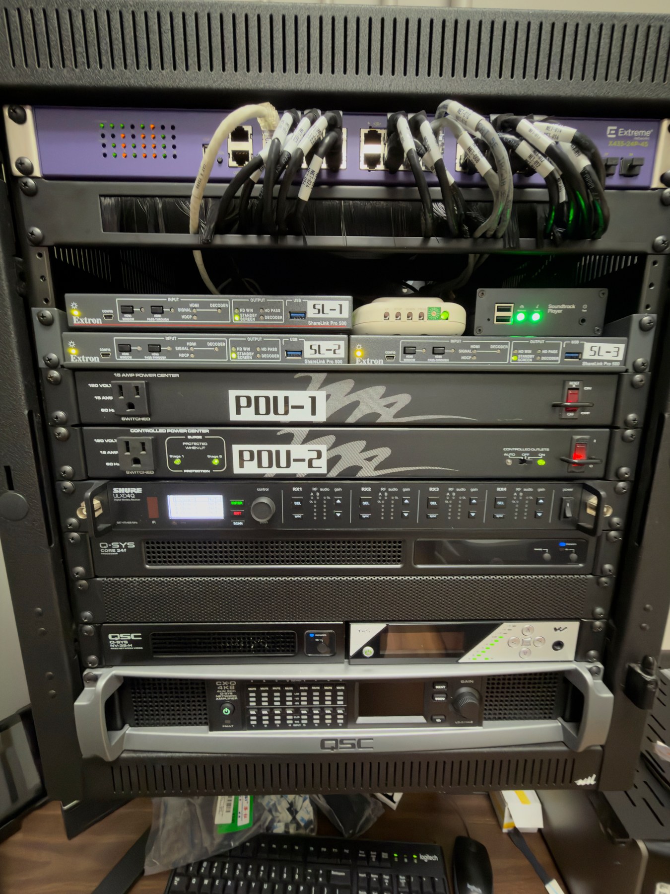
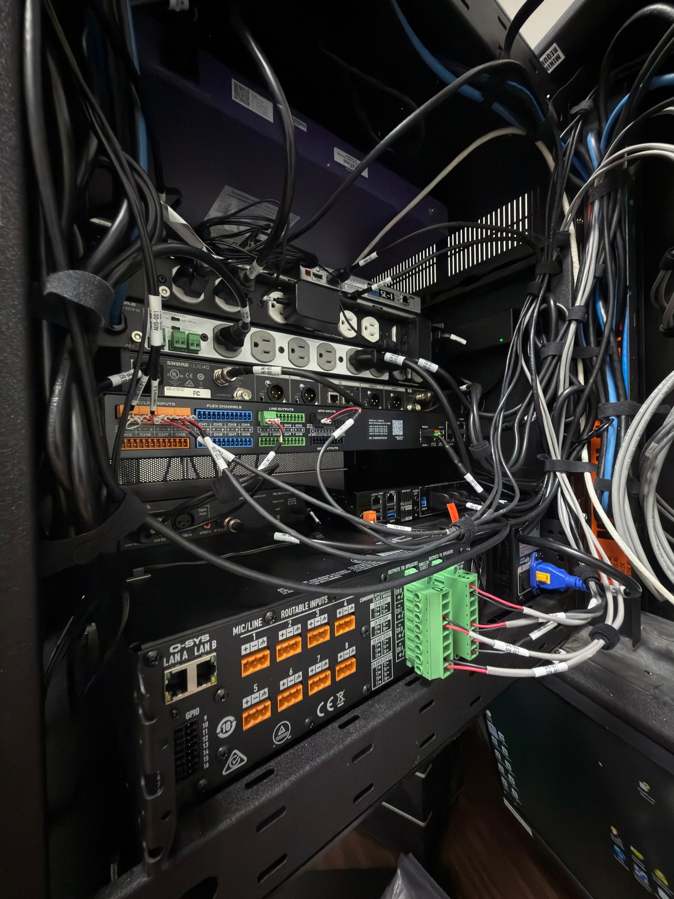
Field work turned the documented system into installed hardware. The images preserve the starting rack, the active installation state, and the wall work behind the finished control surfaces.
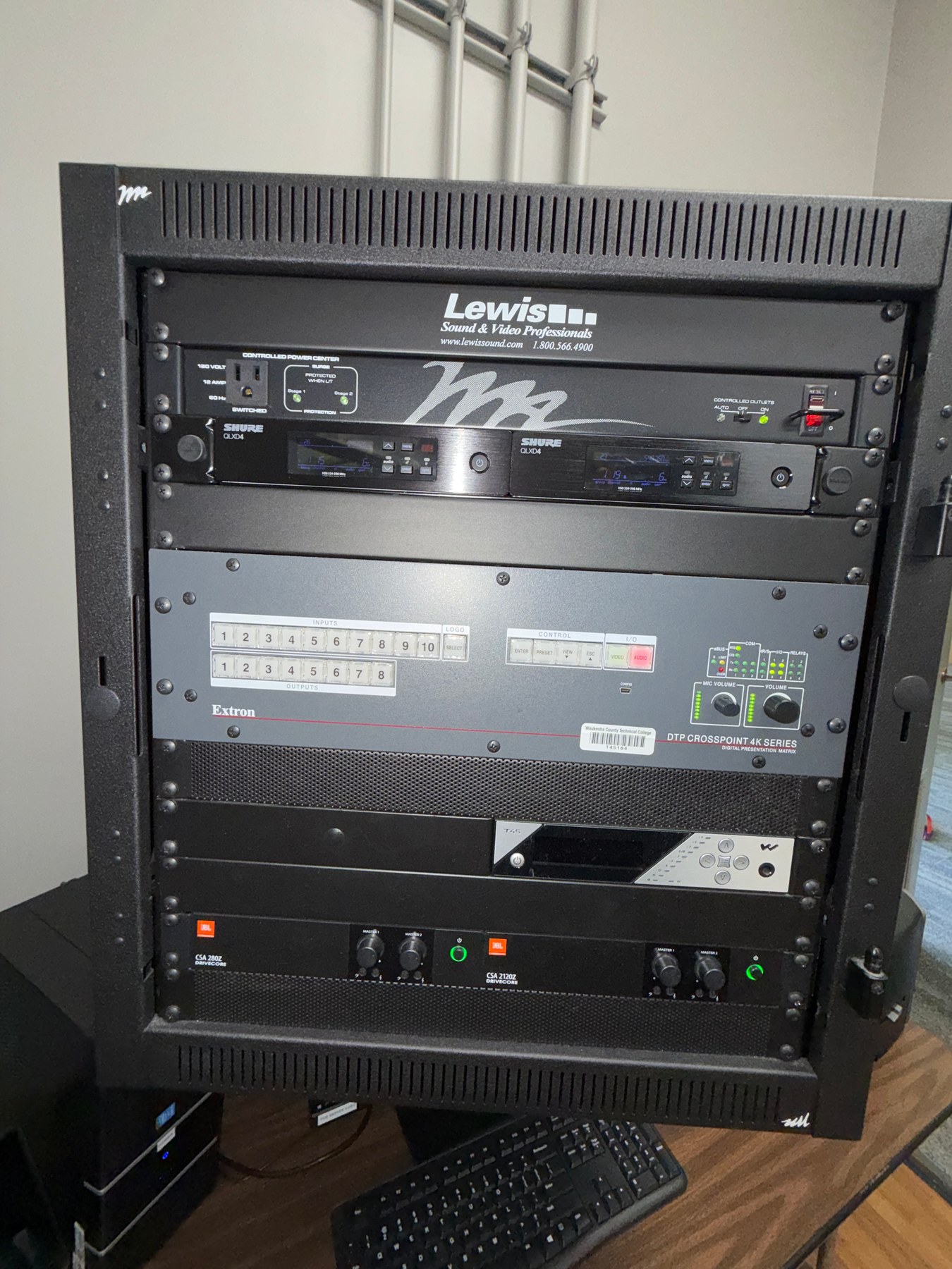
Previous Classic Room equipment rack before the Q-SYS system installation
01 · Previous systemThe earlier rack centered on a hardware matrix and button-based control architecture.
Rear of the Classic Room equipment rack during installation with labeled audio, network, control, and loudspeaker connections
02 · InstallationLabeled connections and documented signal paths made the dense rear-rack work traceable.
Open wall locations and labeled cabling during installation of a Classic Room touch panel and wall-plate connections
03 · In the roomOpen walls, labeled cable runs, and temporary test connections show the work hidden by the finished interface.

Project by the numbers

The scale behind
the screen.

These figures come from the active scripts, Q-SYS archive, mounted interface style, handoff log, and a time study that cross-referenced Q-SYS saves, Sketch Cloud history, and timestamped project notes.

~191.2

hours invested

Estimated across 47 distinct working days from October 2025 through July 15, 2026. The total now includes 13 additional hours logged Monday through Wednesday: six hours Monday, six Tuesday, and one Wednesday.

6,005

lines of active Lua scripts

Across six active scripts, now including System Verification and proportional meter proxies.

386

Q-SYS snapshots

Dated design saves preserve the evolution of the Core file from November 2025 onward.

300

handoff entries

Decisions, fixes, audits, discoveries, and stopping points captured in the shared project log.

1,859

lines of interface styling

Cascading Style Sheets define the visual system that translates the Sketch design language into Q-SYS controls.

466

interface image assets

Buttons, indicators, panels, fader layers, warnings, and supporting graphics in the mounted style.

One more fact The largest active script—the Room Session Engine—is 3,760 lines by itself, coordinating room groups, audio, displays, microphones, shades, navigation, safe shutdown, special-event mode, and verification lockout.
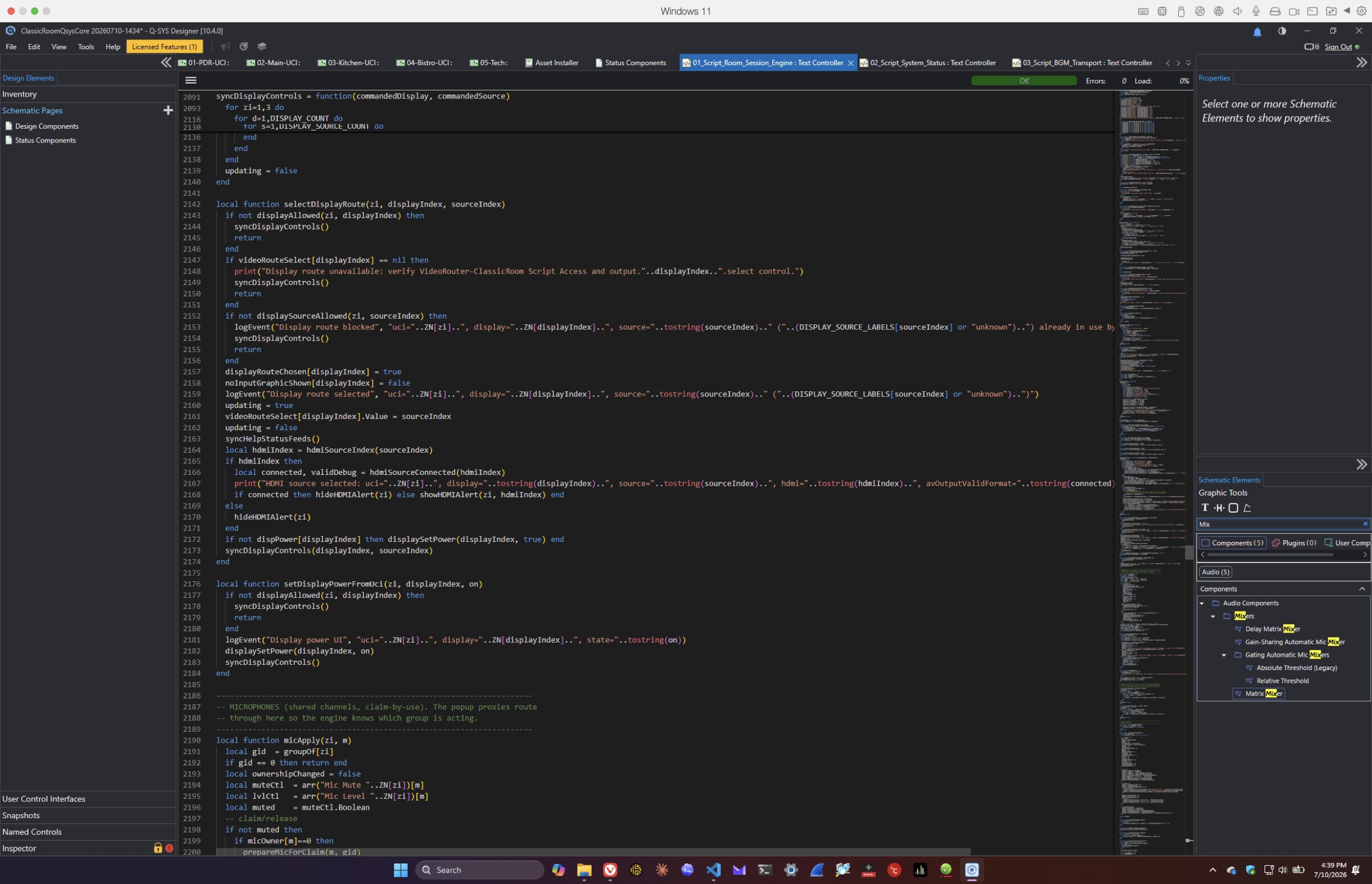
The Room Session Engine Lua source code open in the Q-SYS Designer Text Controller
The coordination layerA view into the 3,760-line Room Session Engine while it validates display routing, synchronizes panel state, checks HDMI signals, controls display power, manages shared microphones, and protects technician-only verification mode.

01 / The record

More than a change log.

This chronology reconstructs the design history from the live AI-to-AI handoff record, installation documentation, and 386 dated Q-SYS design snapshots. It groups hundreds of small revisions into the intervals where the system materially changed.

Nov 18, 2025First archived design

Foundation

The system record begins

The earliest surviving design snapshot establishes the starting point for a multi-room audio-visual system serving the Private Dining Room, Main room, Kitchen, and Bistro.

Read the work behind this milestone
  • A Q-SYS Core 24f—the central processor in a networked audio, video, and room-control platform—anchors control and audio processing.
  • Later snapshots through December, January, February, March, and April show sustained design work well before the formal artificial-intelligence handoff log began.
Jun 1, 2026v0.1.1–v0.1.9

Foundation

A durable project memory is created

Existing Q-SYS help, Sketch export knowledge, scripts, and prior chat histories were consolidated into a structured project record.

Read the work behind this milestone
  • Sketch Model Context Protocol (MCP), which lets software inspect the design document, and the mounted ClassicRoom Q-SYS style directory were verified.
  • A User Control Interface (UCI) asset and script completion matrix exposed what was complete, missing, or obsolete.
  • The ai2ai handoff log was created so work could move reliably between Steve, Codex, and Claude.
Jun 2–3v0.2.1–v0.3.7

System architecture

Zone linking becomes the organizing model

The team pivoted from simple zone selection to a linked-room model with shared resources, coordinated panels, and a defined startup/shutdown state machine.

Read the work behind this milestone
  • Audio, video, display routing, and group membership rules were resolved before implementation.
  • The first Zone Link Engine was written, Sharp display serial behavior documented, and display power-on timing added.
  • Work shifted from speculative UX into a buildable Q-SYS control contract.
Jun 4–5v1.0.1–v1.0.28

Interface build

The redesigned UCI takes physical shape

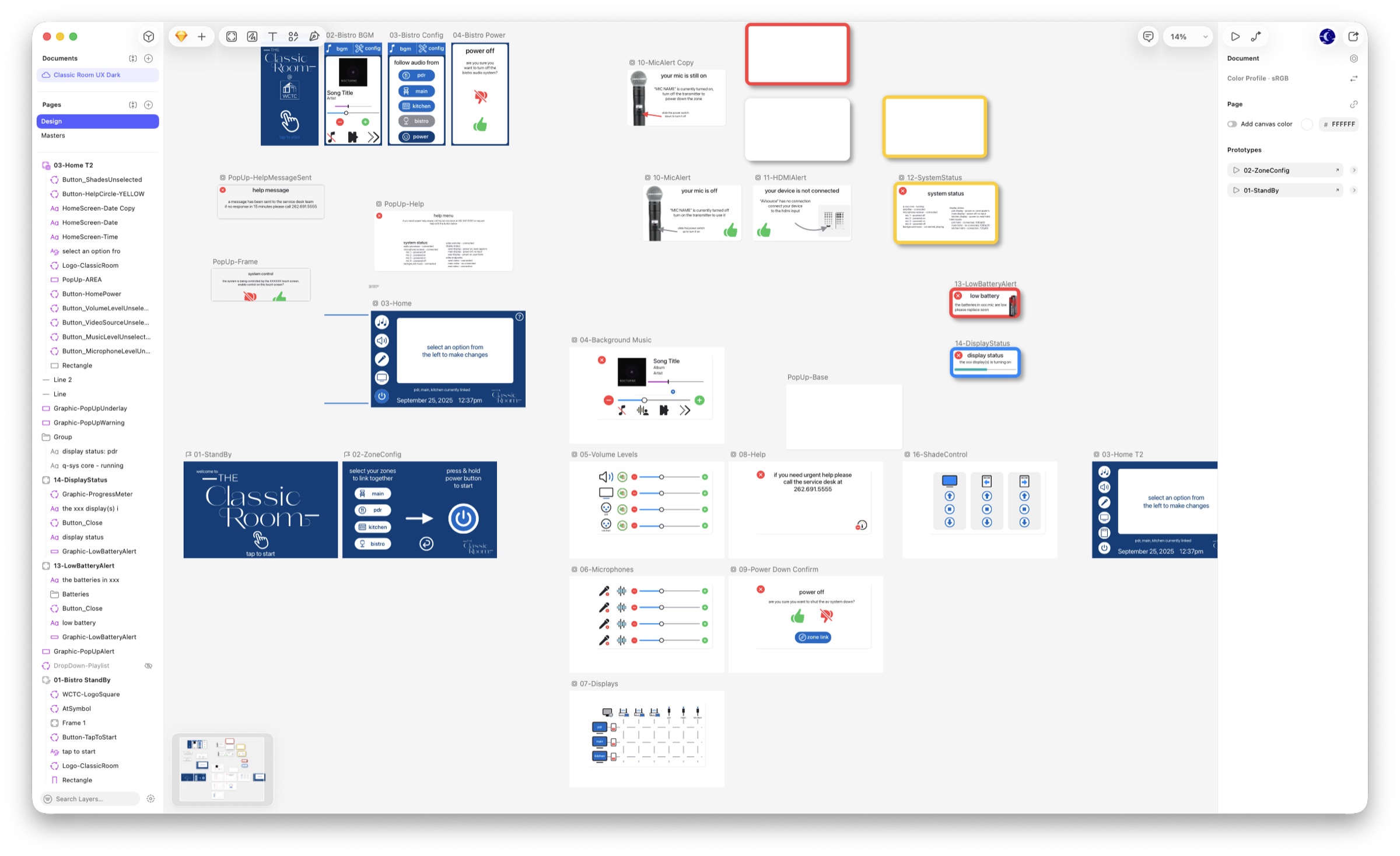
Sketch artwork, Q-SYS Cascading Style Sheets (CSS), page naming, control bindings, and repeatable placement instructions were aligned into the first full interface system.
Read the work behind this milestone
  • The StandBy, ZoneConfig, Home, and Background Music screens were exported and documented.
  • Faders were rebuilt as layered track, meter, and cap assets; typography and image color profiles were normalized for Q-SYS.
  • Crash-prone selectors and naming mismatches were found early and corrected.
Classic Room interface screens and alert designs arranged across the Sketch design canvas
The interface family takes shape in Sketch before implementation in Q-SYS.
Jun 8–9v1.1.1–v1.2.41

Interface build

Core room controls become a coherent experience

Volume, microphone, display, power-down, Help, background music, and Bistro experiences were built as a connected set rather than isolated screens.

Read the work behind this milestone
  • Gain controls gained mute, step, hold-to-ramp behavior, and consistent dB ranges.
  • Display routing enforced one source per destination and dimmed unavailable destinations for linked groups.
  • Bistro received a portrait UCI and audio-follow routing through a final 4×1 router.
  • A power-down confirmation workflow and the first Help/status foundation completed the main navigation arc.
Jun 10–11v1.3.1–v1.4.19

Integration

Live device feedback enters the interface

The UCI began responding to real system conditions: microphone transmitters, High-Definition Multimedia Interface (HDMI) signal validity, display warmup, linked zones, shades, and device status.
Read the work behind this milestone
  • The Bistro power-layer fault and a Q-SYS Lua scripting-language local-variable limit were diagnosed and fixed.
  • Microphone-off and HDMI-not-connected alerts were designed, exported, wired, and hardened against inconsistent displayed values.
  • Main display shade automation, standby-capable wall-switch requests, ZoneConfig relink behavior, video freeze, and live Help status were added.
  • A formal versioning methodology made the running system state visible on the status page.
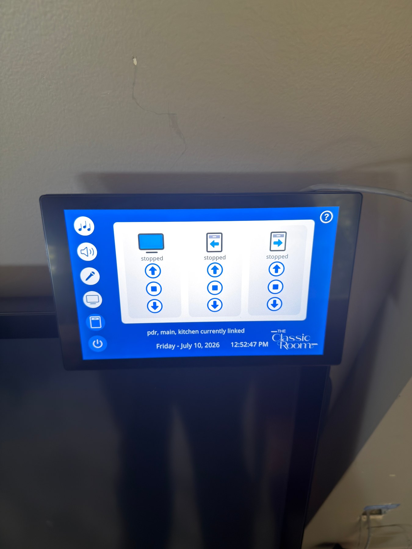
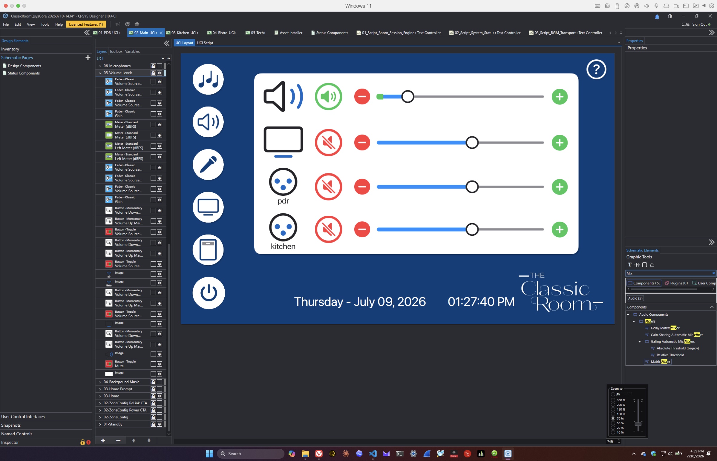
Classic Room volume interface implemented inside Q-SYS Designer
The flat interface language becomes a working control surface with live level and mute states.
Jun 24–26v1.4.20–v1.4.34

Integration

Diagnostics and meters make the system observable

After a short pause, work resumed with discovery diagnostics, system-status popups, Soundtrack controls, field notes, and reliable microphone metering.

Read the work behind this milestone
  • Temporary UCI build modes and discovery dumps isolated Q-SYS 10.4 layer-name issues.
  • System Status, low-battery, display-warmup, and Help recommendations were expanded.
  • Signal-tag-fed microphone meter proxies replaced less reliable approaches.
  • The Soundtrack player received a play/pause proxy and static-IP installation note.
Jun 28v1.4.34–v1.4.36

Reliability

Design polish gives way to field readiness

The interface was visually refined while the project simultaneously moved toward installation planning, independent review, and rollback-safe changes.

Read the work behind this milestone
  • Split-layer faders were built in Designer and matched to new CSS classes.
  • Display routing was remapped around a Q-SYS flex-box limitation.
  • The end-user guide was generated and finalized in Illustrator.
  • A room-by-room solo-install checklist was created, with the speaker-line voltage decision explicitly deferred to field load verification.
Previous Classic Room equipment rack before installation of the Q-SYS control system
The previous rack documents the physical starting point before field replacement began.
Jun 30v1.4.54–v1.4.67

Safety behavior

Shutdown becomes aware of microphones and audio state

A concentrated day of reliability work turned shutdown into a deliberate safety sequence instead of a simple screen transition.

Read the work behind this milestone
  • A non-bypassable reminder blocks shutdown until relevant wireless microphone transmitters are physically off.
  • Recently used and muted transmitters remain tracked so they cannot silently escape the shutdown check.
  • Background music (BGM) and microphone fader ranges, nominal values, startup mute behavior, and hard-floor mute logic were aligned.
  • Multiple Q-SYS local-variable-limit faults were removed without reducing functionality, then the current scripts were independently validated.
Jul 1–2v1.5.0–v1.5.1

Installation readiness

Shade control and amplifier planning are resolved

The shade design expanded from a single legacy path into a documented three-shade Somfy serial system, while audio output planning became installation-ready.

Read the work behind this milestone
  • Nine discrete Somfy Universal Radio Technology Somfy Interface II (URTSI II) commands were assigned across display, left-window, and right-window shades.
  • Serial end-of-line behavior was hardened for Q-SYS and all three shades were proven through shared UCI controls.
  • The obsolete General-Purpose Input/Output (GPIO) command path was removed while wall-switch request inputs were preserved.
  • A JBL tap/load matrix and Q-SYS CX-Q amplifier recommendation documented the speaker-load strategy; AudioPlate signal mapping was corrected.
Open touch-panel wall location with labeled cable and temporary test connections during installation
Labeled field wiring connects the documented control design to the physical room.
Jul 6–8v1.5.2–v1.6.8

System refinement

The design adapts to the final signal and source model

Amplifier outputs, hearing assist, source naming, exclusive routing, technical access, and the user guide were brought into alignment.

Read the work behind this milestone
  • The CX-Q 4K8 parallel-channel plan, terminal wiring, zone taps, and hearing-assist feed were documented in the design.
  • Apple TV naming was replaced with neutral ShareLink and Rack-HDMI terminology.
  • ShareLink and HDMI sources gained exclusive lockout across active groups.
  • A short press now opens System Status while a five-second hold opens the Tech UCI on full-size touchscreens.
  • The User Guide and Sharp display input documentation were updated, including the HDMI2/INPS0013 control contract.

02 / Where it stands

Current handoff · v1.6.28

Built to operate, adapt, and be measured.

The control system is now organized around six active scripts, a versioned UCI/CSS system, solar-aware window-shade automation, live Reflect health, proportional meters, installation records, and a protected loudspeaker-verification workflow. The newest saved design is documented and validated while the remaining physical commissioning boundaries stay explicit.